


Share:
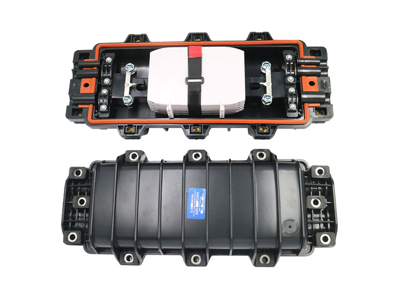
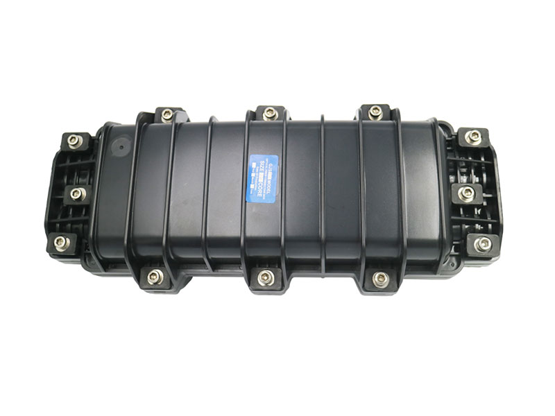
Horizontal Closure,AT-FOSC-H010,Protection Grade:IP68,Number ofports:6 Pieces:3 inlet+3 outlet ,Diameter of fiber optic cable:Φ8—Φ20MM,Max.Capacity: (Bunchy:96Cores,Ribbon:Max.144Cores).12 Core or 24 Core Splice Tray is Optional,(xCore=x*12Core Splice Tray,xCore=x*24Core Splice Tray),Outside Dimension(LxWxH): 430×180×125MM.Weight:2.5-2.825Kg.
1 . Scope of application
This Installation Manual is suit for the Fiber Optic Splice Closure (Hereafter abbreviated as FOSC) , as the guidance of proper installation.
The scope of application is: aerial, underground, wall-mounting, duct-mounting, handhole-mounting. The ambient temperature ranges from -40℃ to +65℃.
2. Basic structure and configuration
2.1 Dimension and capacity
|
Outside dimension (LxWxH) |
470x1 80x1 25 (mm) |
|
Weight (excluding outside box) |
2500g-2825g |
|
Number of inlet/outlet ports |
3 (pieces) on each side (total 6 pieces) |
|
Diameter of fiber cable |
Φ8—Φ20 (mm) |
|
Capacity of FOSC |
Bunchy: 1 2—96 (Cores) Ribbon: max. 1 44(Cores) |
2.2 Main components
|
No. |
Name of components |
Quantity |
Usage |
Remarks |
|
1 |
Housing |
1 set |
Protecting fiber cable splices in whole |
Internal diameter: 430x1 80x63(mm) |
|
2 |
Fiber optic splice tray (FOST) |
max. 6 pcs (bunchy) max. 4pcs (ribbon) |
Fixing heat shrinkable protective sleeve and holding fibers |
Suitable for: Bunchy:1 2,24(cores) Ribbon:3 (pieces) |
|
3 |
Foundation |
1 set |
Fixing reinforced core of fiber- cable and FOST |
|
|
4 |
Seal fitting |
1 set |
Sealing between FOSC cover and FOSC bottom |
|
|
5 |
Port plug |
6 pieces |
Sealing empty ports |
|
|
6 |
Pressure testing valve |
1 set |
After injecting air, it is used for pressure testing and sealing testing |
Configuration as per requirement |
|
7 |
Earthing deriving |
1 set |
Deriving metallic components of fiber cable in FOSC for earthing |
Configuration as per requirement |
1
|
|
device |
|
connection |
|
2.3 Main accessories and special tools
|
No. |
Name of accessories |
Quantity |
Usage |
Remarks |
|
1 |
Heat shrinkable protective sleeve |
|
Protecting fiber splices |
Configuration as per capacity |
|
2 |
Nylon tie |
|
Fixing fiber with protective coat |
Configuration as per capacity |
|
3 |
Insulation tape |
1 roll |
Enlarging diameter of fiber cable for easy fixing |
|
|
4 |
Seal tape |
1 roll |
Enlarging diameter of fiber cable which fits in with seal fitting |
Configuration as per specification |
|
5 |
Hanging hook |
1 set |
For aerial use |
|
|
6 |
Earthing wire |
1 piece |
Putting through between earthing devices |
|
|
7 |
Abrasive cloth |
1 piece |
Scratching fiber cable |
|
|
8 |
Labeling paper |
1 piece |
Labeling fiber |
|
|
9 |
Special wrench |
3 pieces |
Fixing bolts, tightening nut of reinforced core |
|
|
10 |
Measuring paper |
1 piece |
To measure circle, of which its diameter is enlarged with seal tape |
|
|
11 |
Buffer tube |
to be decided by customers |
Hitched to fibers and fixed with FOST, managing buffer |
Configuration as per requirement |
|
12 |
Desiccant |
1 bag |
Put into FOSC before sealing for desiccating air. |
|
3. Necessary tools for installation
3.1 Supplementary materials (to be provided by operator)
|
Name of materials |
Usage |
|
Scotch tape |
Labeling, temporarily fixing |
|
Ethyl alcohol |
Cleaning |
|
Gauze |
Cleaning |
3.2 Special tools (to be provided by operator)
|
Name of tools |
Usage |
|
Fiber cutter |
Cutting off fibers |
|
Fiber stripper |
Strip off protective coat of fiber cable |
|
Combo tools |
Assembling FOSC |
3.3 Universal tools (to be provided by operator)
|
Name of tools |
Usage and specification |
|
Band tape |
Measuring fiber cable |
|
Pipe cutter |
Cutting fiber cable |
|
Electrical cutter |
Take off protective coat of fiber cable |
|
Combination pliers |
Cutting off reinforced core |
|
Screwdriver |
Crossing/Paralleling screwdriver |
|
Scissor |
|
|
Waterproof cover |
Waterproof, dustproof |
|
Metal wrench |
Tightening nut of reinforced core |
3.4 Splicing and testing instruments (to be provided by operator)
|
Name of instruments |
Usage and specification |
|
Fusion Splicing Machine |
Fiber splicing |
|
OTDR |
Splicing testing |
|
Provisional splicing tools |
Provisional testing |
Notice: The above-mentioned tools and testing instruments should be provided by the operators themselves.
4. Installation flow chart
5. The process of installing FOSC
Step One - Open the closure
Cleaning the locale and determine where to install the FOSC and then place fiber cables required.
Check whether the main components and accessories have been well prepared inside the package.
Open the closure
Unscrew fixing bolts and open the closure by lifting the unscrewed bolts with no need completely unbolting to avoid loosing.
See Drawing 1
Important issues: If the weather condition is not good enough, then a tent must be pitched
for waterproof and dustproof.
YOUR VACATION IS HERE
Prepare your network for seamless 5G deployment. Get direct access to factory pricing, custom OEM/0DM solutions, and rapid prototyping,
Let's Build Your Optical Network, Kindly have a chat with our sales experts!
Get A Free Quote
Related Products

1+3 Inlet/outlet 48Cores Dome Type Fiber Joint Box
Alteoptic Model No. SC-ATD048-01 is one of the main equipment for user access points, applied for protective connection and distribution between two or more cables. The primary function is to connect distribution cable and indoor cable in the open air. It’s widely used in communication systems, cable TV, optical cable network systems and others by virtue of steady structure, good sealing performance and easy construction.
View More
1+4 Inlet/outlet Vertical Type 288Core Dome Splice Closure
Alteoptic Model No. SC-ATD288-01 is one of the main equipment for user access points, applied for protective connection and distribution between two or more cables. The primary function is to connect distribution cable and indoor cable in the open air. It’s widely used in communication systems, cable TV, optical cable network systems and others by virtue of steady structure, good sealing performance and easy construction.
View More
1+16 Inlet/outlet Heat shrinkable 144cores Access Points Splice Closure
Model No. SC-ATD144-05 is one of the main equipment for user access points, applied for protective connection and distribution between two or more cables. The primary function is to connect distribution cable and indoor cable in the open air. It’s widely used in communication systems, cable TV, optical cable network systems and others by virtue of steady structure, good sealing performance and easy construction.
View More
No. SC-ATH096-05 is one of the main equipment for user access points, applied for protective connection and distribution between two or more cables. The primary function is to connect distribution cable and indoor cable in the open air. It’s widely used in communication systems, cable TV, optical cable network systems and others by virtue of steady structure, good sealing performance and easy construction.
View More
High Proformance 25 Port 144 Core Fiber Optic Splice Closure For Outdoor
Alteoptic Model No. SC-ATH144-04 is one of the main equipment for user access points, applied for protective connection and distribution between two or more cables. The primary function is to connect distribution cable and indoor cable in the open air. It’s widely used in communication systems, cable TV, optical cable network systems and others by virtue of steady structure, good sealing performance and easy construction.
View More
Alteoptic is one of the main equipment for user access points, applied for protective connection and distribution between two or more cables. The primary function is to connect distribution cable and indoor cable in the open air.
View More
SC-ATH096-10 3+3 Inlet/outlet Strong Structure 96core Cable Joint Box
Alteoptic Model No. SC-ATH096-10 is one of the main equipment for user access points, applied for protective connection and distribution between two or more cables. The primary function is to connect distribution cable and indoor cable in the open air. It’s widely used in communication systems, cable TV, optical cable network systems and others by virtue of steady structure, good sealing performance and easy construction.
View More
120 Cores Horizontal 3 In 3 Out Fiber Optic Splice Enclosure
This FTTH fiber optical mini dome ftth aerial cheap closures can be placed in aerial, underground, wall-mounting, hand hole mounting and duct-mounting applications.The strong housing and main components provide fire resistant, waterproof and quakeproof while protecting splices during pulling, torsioning and impacting. It ensures long term reliability and usage under ambient temperature from -40℃ to +65℃.
View More
2+2 Inlet/outlet Horizontal Type 144 Cores Optic Closure Box
Optic fiber clousure is applied in the junction and protecting of the fiber.It can be place with the aerial cable or buried in earth or put in the pipeline.The outer part and the fusing part of the clousure are made of the project plastic with the virtue .
View More
The optical cable splicing box can be used for fusion splicing of part of the main optical cable and branch optical cable, part of the main optical cable and pigtail or pigtail cable at the same time, and connected to the optical switching equipment through the jumper fiber. The welding unit, wiring unit, part of the material of the network box shell, the optical cable from the optical cable connection box to the network box and the entire operation process can be omitted.
View More