


Sep.30,2026
Share:
A field technician is on the last mile of an FTTH installation. The drop cable is already inside the customer's home. The fiber is prepared. But the final connection still needs a reliable termination. If the connector fails, the technician has to cut the fiber, re-cleave it, and start again. That costs time and frustrates the customer. In rural broadband projects, the nearest workshop may be an hour away. Every failed connector adds a full round trip. This is why field-installable fast connectors matter. They let the technician complete a stable optical connection on site, without returning to the workshop. We are currently preparing a batch of these connectors for a customer in the United Kingdom. Let me show you how we make them.
This order includes two compact fast connector models: the LN-01-60 with a 60-millimeter body and the LN-10 with a 50-millimeter body. Both work with single-mode G.657A2 fiber and common FTTH drop cables. They support wavelengths of 1310, 1490, and 1550 nanometers. The average insertion loss is no more than 0.3 dB. Assembly takes about 50 seconds. Each connector can be reused at least ten times.
Our customer in the UK supplies installation teams working on residential estates, apartment buildings, and rural broadband expansion. His technicians needed a connector that was fast to install and reliable in different environments. They work in houses, utility rooms, building risers, and outdoor cabinets. The connector has to handle all of these conditions. We proposed the LN-01-60 and LN-10 models. Both passed the customer's sample evaluation. Now the full batch is in production. Here is the process behind every connector.
The first question a buyer asks about a fast connector is simple. What cable does it work with? A connector that fits one cable type but not another creates confusion in the field. The technician has to check the cable, check the connector, and sometimes search for a different part. We designed both the LN-01-60 and LN-10 to work with the most common FTTH cable types used in UK deployments.
The LN-01-60 has a 60-millimeter body. The LN-10 has a 50-millimeter body. Both are designed for single-mode G.657A2 fiber. They work with 3.0 by 2.0 millimeter flat drop cable, 3.0 millimeter round cable, 2.0 millimeter indoor cable, and 0.9 millimeter buffered fiber.
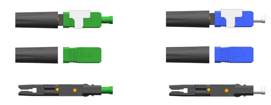
The two models cover different installation preferences. Some technicians prefer a shorter body for tight spaces. Others prefer a longer body for easier handling. Both use the same G.657A2 bend-insensitive fiber. This fiber type is common in FTTH networks because it tolerates tight bends without high signal loss. The table below shows the cable types each connector supports.
| Cable Type | Diameter | Common Use |
|---|---|---|
| Flat drop cable | 3.0 x 2.0 mm | Outdoor to indoor transition |
| Round drop cable | 3.0 mm | Aerial and duct installation |
| Indoor cable | 2.0 mm | Inside buildings |
| Buffered fiber | 0.9 mm | Patch panels and equipment rooms |
Fast connectors are used at the customer side of the network. The drop cable comes from a street cabinet, a distribution point, or a splitter. The technician brings the cable into the home or business. Then he prepares the fiber and installs the connector. The table below shows common installation locations.
| Location | Why Fast Connectors Help |
|---|---|
| Residential estates | Quick termination at each home |
| Apartment buildings | Multiple floors, limited workspace |
| Small commercial properties | Fast setup for business service |
| Rural broadband | Long distances, no nearby workshop |
For UK FTTH projects, this product supports last-mile deployment. It reduces the need for fusion splicing equipment at the customer premises. The technician can complete the connection with simple tools and move to the next job.
A fast connector looks simple from the outside. Inside, it has precision parts that must align the fiber correctly. If the internal components are not molded to tight tolerances, the fiber will not sit in the right position. The connection loss will be high. The connector may fail after a few mating cycles. That is why we control the production from the injection molding stage.
Our injection molding area produces the black connector housings and internal plastic components. The molded parts are checked and sorted before assembly. On the production floor, our operators assemble internal components, fiber-holding parts, protective caps, locking elements, and connector housings using organized material trays and inspection equipment.
The black connector housing forms the outer protection and cable-management structure. We mold it from high-strength plastic. After molding, every batch goes through a visual and dimensional check. The internal plastic components are also inspected. These parts hold the fiber in alignment and lock the cable in place. The table below shows the main components we produce in-house.
| Component | Function |
|---|---|
| Outer housing | Protects internal parts and holds the cable |
| Fiber holder | Aligns the fiber in the correct position |
| Locking element | Secures the cable after insertion |
| Protective cap | Covers the ferrule before installation |
| Inner body | Guides the fiber during assembly |
The assembly area is organized for efficiency and accuracy. Operators work with material trays that hold each component type. They assemble the connector step by step. The goal is not only to make the connector look complete. The goal is to make sure it performs consistently when a technician uses it in the field. The table below shows the assembly sequence.
| Step | Action |
|---|---|
| 1 | Insert fiber holder into inner body |
| 2 | Install locking element |
| 3 | Place assembly into outer housing |
| 4 | Attach protective cap |
| 5 | Visual check and functional test |
Each connector is checked before it moves to packaging. We look for correct assembly, smooth locking action, and clean appearance. A connector with a loose part or a misaligned component is pulled from the line.
A fast connector must do two things. It must transfer the optical signal with low loss. And it must keep working after installation, through temperature changes, humidity, and regular handling. These two requirements are tested separately. Both matter for long-term network reliability.
The connectors in this batch are designed for 125-micron fiber and operate at 1310, 1490, and 1550 nanometers. The average insertion loss is specified at no more than 0.3 dB, with a maximum of 0.5 dB. Return loss is at least 50 dB for UPC versions and at least 55 dB for APC versions.
Insertion loss measures how much optical power is lost through the connection. Return loss measures how much light is reflected back. For FTTH and GPON networks, both values matter. The table below shows the optical specifications for this batch.
| Parameter | Specification |
|---|---|
| Fiber type | Single-mode G.657A2 |
| Fiber diameter | 125 microns |
| Operating wavelengths | 1310, 1490, 1550 nm |
| Average insertion loss | ≤ 0.3 dB |
| Maximum insertion loss | ≤ 0.5 dB |
| Return loss (UPC) | ≥ 50 dB |
| Return loss (APC) | ≥ 55 dB |
These numbers help ensure that the connection transfers the optical signal efficiently and keeps reflected light under control. In a PON network, too much reflection can affect other subscribers on the same splitter. Low return loss keeps the network stable.
The connector must survive real installation conditions. Technicians pull cables, bend them around corners, and handle connectors many times. The connector also faces temperature changes and humidity. The table below shows the tests this product is designed to pass.
| Test | Condition | Requirement |
|---|---|---|
| Tensile strength | 2 x 3 mm drop cable | ≥ 45 N |
| Online tensile loading | During operation | Stable optical performance |
| Mechanical durability | Repeated handling | No degradation |
| Vibration | Simulated transport | IL variation ≤ 0.3 dB |
| Torsion | Twisting force | No damage |
| Drop test | Accidental drops | No breakage |
| High temperature | +85°C | IL variation ≤ 0.3 dB |
| Low temperature | -40°C | IL variation ≤ 0.3 dB |
| Temperature cycling | Hot to cold cycles | IL variation ≤ 0.3 dB |
| Humidity | High humidity | IL variation ≤ 0.3 dB |
| Immersion | Water exposure | IL variation ≤ 0.3 dB |
| Salt mist | Corrosive environment | IL variation ≤ 0.3 dB |
The operating temperature range is minus 40 to plus 85 degrees Celsius. This covers the conditions found in UK installations, from cold utility rooms to hot outdoor cabinets. After all these tests, the connector is expected to keep insertion-loss variation within 0.3 dB.
Speed and reliability are the two things field technicians care about most. A connector that takes ten minutes to install slows down the whole project. A connector that fails after one week creates a service call. The fast connector design addresses both concerns. It reduces installation time and provides a stable connection that lasts.
After the fiber has been prepared, the connector can normally be assembled in around 50 seconds. The design supports repeated use, with a minimum of ten reuses. This gives field teams more flexibility during installation and maintenance work.
The technician prepares the fiber, cleaves it, inserts it into the connector, and locks it in place. The whole process takes about 50 seconds. The table below shows the basic steps.
| Step | Action | Time |
|---|---|---|
| 1 | Strip the cable jacket | 10-15 seconds |
| 2 | Clean the fiber | 5-10 seconds |
| 3 | Cleave the fiber | 5-10 seconds |
| 4 | Insert into connector | 5 seconds |
| 5 | Lock and verify | 10 seconds |
| Total | Complete termination | About 50 seconds |
For a project with hundreds of connections, this time saving adds up. The technician can complete more installations per day. The customer gets service faster.
The connector can be reused at least ten times. If the technician makes a mistake during installation, he can unlock the connector, remove the fiber, and try again. This reduces waste. It also helps during maintenance. If a connector needs to be replaced, the technician can reuse the same connector body with a new fiber preparation. The table below shows the reuse benefits.
| Scenario | Benefit of Reusability |
|---|---|
| Installation error | Retry without using a new connector |
| Fiber damage | Replace fiber, keep connector |
| Maintenance visit | Re-terminate without new parts |
| Training | Practice without wasting components |
This flexibility matters in rural broadband projects where the technician may not have easy access to extra parts. It also helps in apartment buildings where the technician works in a small space and cannot afford mistakes.
The final step is packaging. A fast connector is a small part, but it still needs protection during shipping. The packaging must also support efficient warehouse handling for larger project quantities. If the boxes are hard to stack or label, the customer's warehouse team wastes time.
Our team completes visual checks, functional assembly checks, and final packaging work. Connectors are packed in blister boxes, with ten pieces per inner box. Each carton configuration is designed to support efficient shipment and warehouse handling for larger project quantities.
The blister box protects each connector from dust and physical damage. Ten pieces go into one inner box. The inner boxes are then packed into export cartons. The table below shows the packaging details.
| Packing Level | Quantity | Purpose |
|---|---|---|
| Blister box | 1 piece | Protect individual connector |
| Inner box | 10 pieces | Easy counting and distribution |
| Export carton | Custom quantity | Safe sea or air freight |
Before the cartons are sealed, we do a final check. The table below shows the inspection items.
| Check Item | What We Look For |
|---|---|
| Visual appearance | No cracks, scratches, or color defects |
| Assembly completeness | All parts present and correctly fitted |
| Locking action | Smooth and secure |
| Protective cap | Installed and clean |
| Packaging | Blister box sealed, inner box labeled |
| Carton label | Correct model, quantity, and batch number |
For this UK order, every box represents more than a small fiber accessory. It represents the final connection between the fiber network and the end user. A well-made fast connector helps installers save time, reduce rework, and deliver a clean and stable optical connection at the customer premises.
This batch of field-installable fast connectors for the UK covers two models: the LN-01-60 and the LN-10. Both work with common FTTH drop cables and G.657A2 fiber. We produce the internal components in our own injection molding area. We assemble each connector with careful attention to alignment and locking action. We test the optical performance and durability against strict specifications. We pack the connectors in blister boxes and export cartons for safe shipment. At Alteoptic, we support FTTH projects with fast connectors, drop cables, pigtails, patch cords, adapters, PLC splitters, terminal boxes, splice closures, and customized passive fiber solutions. From component production to final inspection and packaging, we focus on supplying practical products for real network deployment. This batch is now moving closer to shipment to the United Kingdom. If you need reliable fast connectors for your FTTH projects, reach out to us.
YOUR VACATION IS HERE
Prepare your network for seamless 5G deployment. Get direct access to factory pricing, custom OEM/0DM solutions, and rapid prototyping,
Let's Build Your Optical Network, Kindly have a chat with our sales experts!
Get A Free Quote
Related Products

Alteoptic S8 side-open fiber thermal stripping pliers feature premium craftsmanship and stable performance. It quickly melts and removes the outer plastic sheath of optical fibers while effectively protecting the internal fiber core from damage. This professional design greatly improves stripping efficiency and ensures excellent fiber quality, making it ideal for reliable optical fiber construction and maintenance.
View More
CFS-2 Two Port Cable Stripper FTTH Fiber Fusion Splicing Tool Bare Fiber Leather Fiber Stripper
CFS-2 is a dual port cable stripper designed specifically for FTTH fiber fusion splicing. It precisely peels off the outer protective jacket and buffer layer of the fiber optic cable. Made of high-quality materials, easy to use, ensuring that the optical fiber is not damaged. The ergonomic handle design provides a comfortable grip and reduces fatigue.
View More
Alteoptic's affordable single head armored fiber optic cable cutter is a stripping tool with a diameter range of 8-28.6mm, which can horizontally and vertically cut fiber optic cables for easy stripping.
View More
Alteoptic's affordable single head armored fiber optic cable cutter is a stripping tool with a diameter range of 4-10mm, which can horizontally and vertically cut fiber optic cables for easy stripping.
View More
The fiber tool loose tube slitting machine is designed specifically for loose tubes with an outer diameter of 1.5-3.3mm. This longitudinal cutter effortlessly peels off the external protective material of the fiber optic central bundle tube. Made of leather, comfortable and durable, ensuring precise and efficient peeling. Whether it's fiber optic installation or maintenance, this loose tube slitting machine is a valuable assistant for professionals.
View More
The Mid-Span Access Tool AUA-05 is designed for cables ranging from 1.9-3.0mm, featuring efficient longitudinal cable cutting. It is ideal for stripping loose-tube armored fiber cables and is available in three colors, offering easy handling for fiber optic installation and maintenance tasks.
View More
8-Port Gel-Sealed Fiber Optic Splice and Patch Closure with SC/APC Adapters
AT01135 Fiber Optic Splice Closure is a wiring line device of user distributions in FTTH system, it provides protection and management for fiber cable, and be used for terminating, cable branching, cross connection.It is mainly used for user access point in FTTH-ODN network , it can be divided into indoor and outdoor type according to the installation scenario, and can be divided into distribution type and optic-split type according to thefunction.AT01135 is used as a termination point for the feeder cable to connect with drop cable in FTTx communication network system. The fiber splicing, splitting, and distribution can be done in this box, and meanwhile it provides solid protection and management for FTTx network building.
View More
10 wavelengths,500 sets of data storage and cyclic overlay, Two types of connectors can be replaced 2.5 mm universal connector for SC/FC/ST/LC (optional)
View More
Support replacement interface, 2.5mm universal interface,Standard Suitable for SC/FC/ST connectors, There is continuous wave output,And comes with 3 modulation frequencies
View More
Automatic switch-off after10 minutes of standby,Stable and powerful light source, strong penetration.and LED for easy line inspection and construction in dark environments
View More